
-
-
Refer to this guide here on modifying the plastic for the auto probe to make it retract easier.
-
-
-
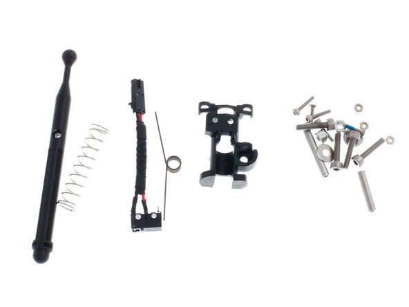
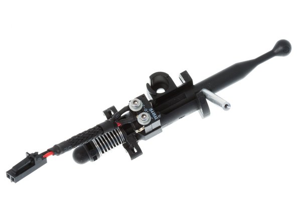
The Auto Levelling Probe subassembly fucntion similarly to a retractable ball point pen.
-
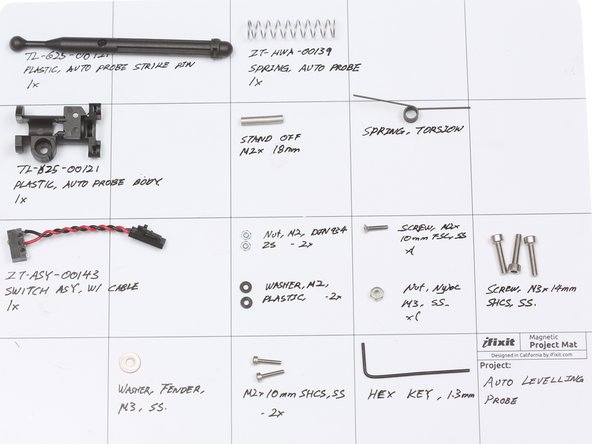
Parts are located in a bag labelled ZT-KIT-00127, located inside the "Kossel Common Core Component Kit".
-
Although the probe was first introduced on the Kossel Pro, it should work well for Cartesian printers as well for probing bed height and setting the first layer.
-
Prior to the start of a print, the probe deploys and triggers a Z-Min end stop. In the deployed position, the probe is lower than the print nozzle, thus allowing the end effector to sense the position of the print bed.
-
Touches to the probe are registered through the Z-Min end stop
-
When the probing is finished, pressing down on the probe locks it into the retracted state.
-
-
-
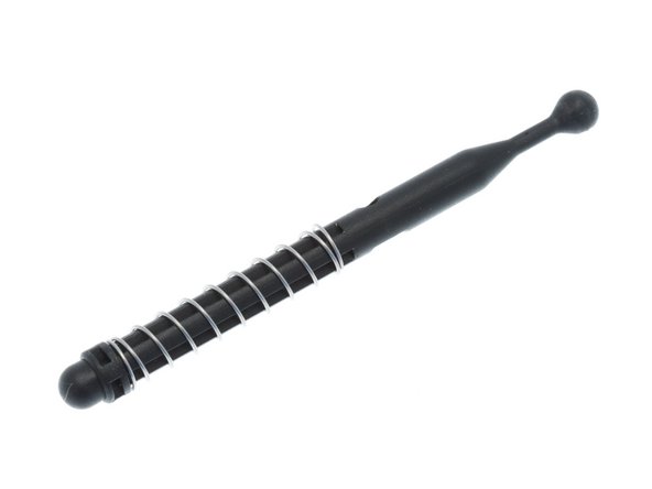
Start by threading the main spring onto the probe strike pin, as shown on the right.
-
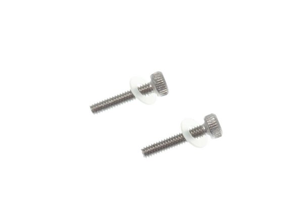
Thread a M2 Plastic Washer onto each of the M2 x 10mm SHCS, as shown on the right.
-
-
-
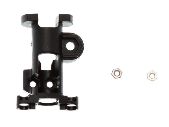
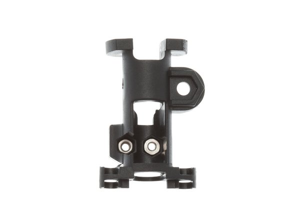
Locate 2x M2 nuts. Flip Auto Probe Body over to expose the 2 hexagonal indentation for the nuts, and insert them, as shown on the right.
-
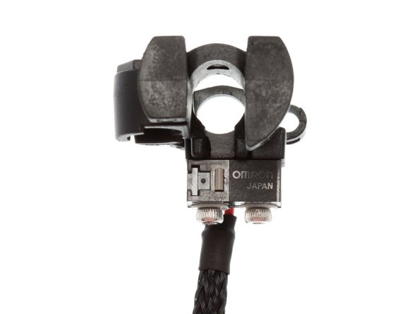
Holding the Auto Probe Body in orientation shown, install the switch with text side facing out, using the M2 x 10mm SHCS + washer hardware stack built on the previous slide.
-
Lightly tighten the screws to finger tight, but do not tighten. For optimal performance, the switch needs to be centered correctly.
-
-
-
Bias the switch so that the actuation tab is roughly centered on the opening for the auto levelling probe.
-
Tighten the M2 x 10mm SHCS to lock the switch in place.
-
-
-
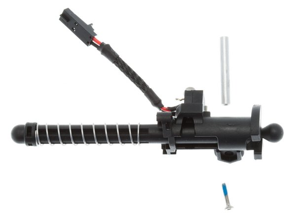
Slide Strike Pin and Spring combination from earlier in the build process onto the Auto Probe Body.
-
While compressing the Strike Pin, place the standoff on the flat side of the Strike Pin. Note: newer versions of this kit ships with 2 standoffs. Use the shorter one for the Mini Kossel, the longer standoff for the Kossel Pro.
-
Insert M2 x 10mm FSC from the countersunk side of the Strike Pin, tightening screw all the way with the supplied 1.3mm hex key. NOTE: newer kits will ship with blue thread locker pre-applied to this screw.
-
NOTE: It is important to lock the stand off in with no movement, by cranking down on the M2 x 10mm as tight as you can. Failure to do so will result in the probe falsely reporting a triggered touch.
-
-
-
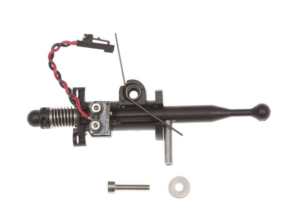
The torsion spring is used to lock the probe into the retracted position when the probe presses down on one of the lock tabs for the HBP / Glass after the end of a G29 routine.
-
Install torsion spring as shown.
-
Secure torsion spring with M3 screw, fender washer and nyloc nut.
-


Cancel: I did not complete this guide.
2 other people completed this guide.