
Introduction
The Cold End, or the Extruder, is the part of the printer that drives the filament into the Hot End, where the filament is melted and deposited onto the model. We will be building a variant of SeeMeCNC’s EzStruder in this slide deck.
Tools
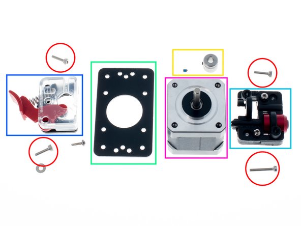
Parts
No parts specified.
-
-
The Cold End, or the extruder, is the part of the printer that drives the filament into the hot end, where the filament is melted and deposited onto the model.
-
We will be building a variant of SeeMeCNC's EzStruder in this guide.
-
In addition to the hex drivers included in the 3D Printer Kit, you will need a Phillips #1 driver to disassemble the SeeMeCNC EzStruder for modifications.
-
-
-
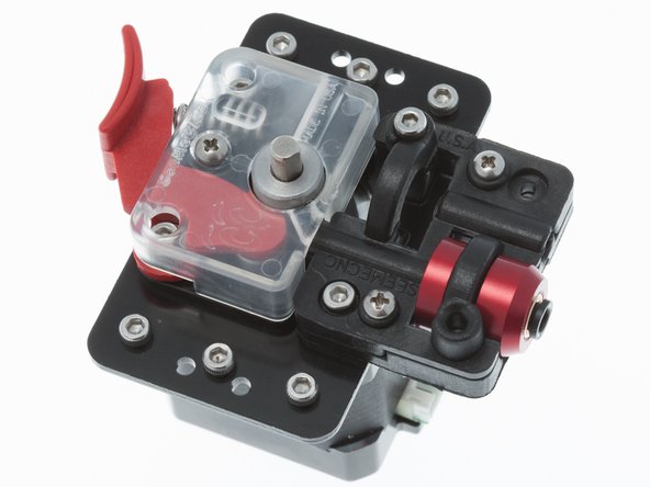
It is helpful to orient the parts as shown to get a better understanding of how the cold end assembly will be going together.
-
The motor connector should face in the same direction as the filament feed.
-
Failure to orient this corectly will require a complete rebuild - the motor and cold end extruder set will not fit through the lower triangle framework.
-
-
-
Bolts (3 M3x12mm and 1 M3x18mm)
-
Hobbed Pulley and M3x4mm Set Screw
-
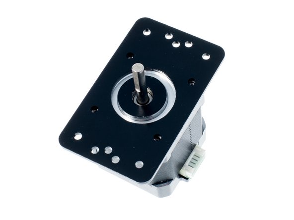
Stepper Motor Mounting Plate
-
EZStruder, Lower
-
EZStruder, Upper
-
NEMA 17 Stepper Motor
-
-
-
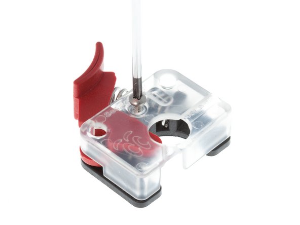
With a #1 Phillips screwdriver, remove the single #1 Phillips drive screw from the SeeMeCNC EzStruder Top.
-
-
-
Place an OpenBeam NEMA17 motor bracket onto a stepper as shown.
-
Note the orientation of the stepper motor's connector.
-
-
-
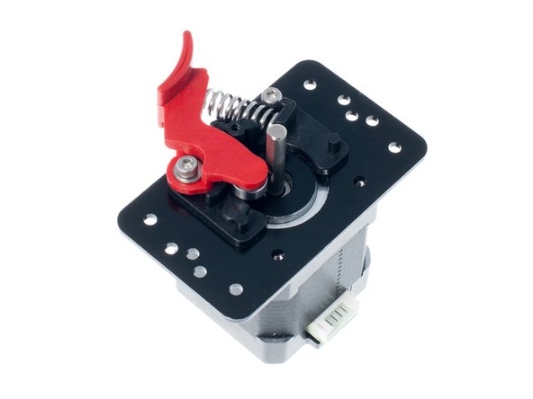
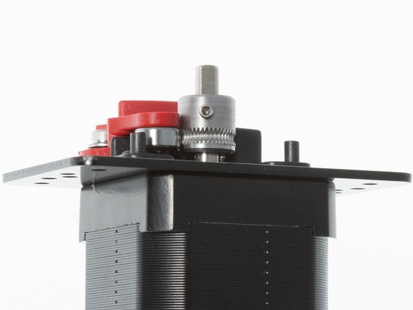
Place the EzStruder Upper parts on as shown
-
Note motor connector orientation
-
Secure with 2x M3 x 12mm SHCS
-
-
-
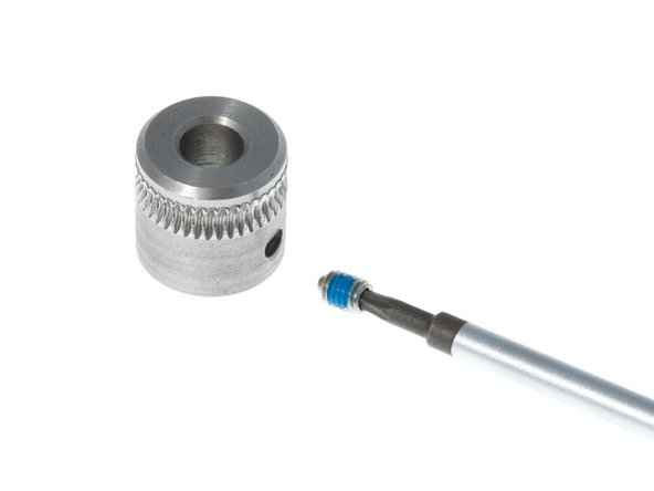
The knurled pulley, sometimes called a hobbed pulley, is what grips the plastic filament for feeding into the printer
-
Remove the M3 set screw that came with the SeeMeCNC kit and reinstall with thread-locking set screw
-
Line up the center of the knurling pattern with the center of the ball bearing. Note the orientation of the pulley. Tighten the set screw down onto the flat of the stepper motor shaft.
-
-
-
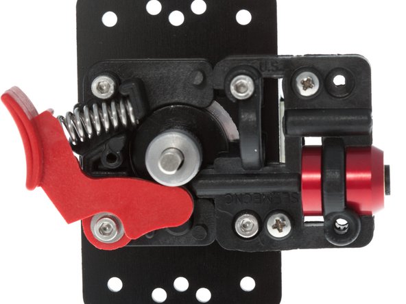
Install 1x M3 x 12mm SHCS and 1x M3 x 18mm SHCS into positions as shown
-
Press spring back into tension lever as shown.
-
-
-
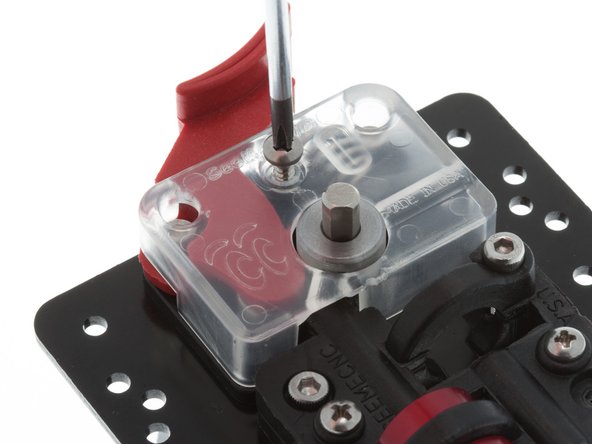
Using #1 Phillips Screwdriver, reinstall plastic cover onto EzStruder.
-
-
-
6x M3 x 6mm SHCS are used to attach the EZStruder subassembly onto the Kossel lower triangle. Using the provided nut, load the screws on and set it aside for safekeeping.
-


Cancel: I did not complete this guide.
3 other people completed this guide.