
-
-
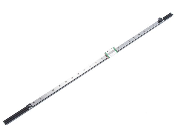
Drive towers are the vertical components on a Kossel frame. Their job is to guide the motion of the carriage up and down.
-
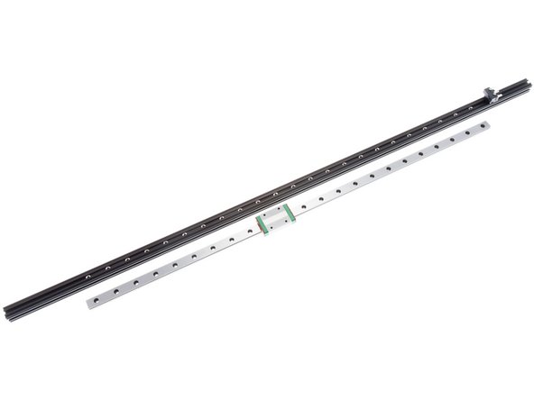
We use induction hardened linear rails to increase the machine's frame rigidity.
-
-
-
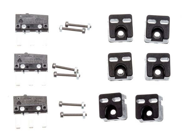
Here are the parts used for this subassembly and the bags that they come from.
-
ZT-KIT-00137 - End Stop Switch Kit - contains: End Stop Switches + mounting nuts and bolts
-
ZT-KIT-00139 - Reprap Fastener Pack - contains: M3 nuts, M3x8mm SHCS, Lock Washers
-
ZT-KIT-00153 - Kossel Sundries - contains: Rail Spacers
-
ZT-KIT-00124 - Kossel Chassis Upgrade Kit - contains: End Stop Switch holder plastics. This part may be replaced by 3D Printed equivalent; see file ZT-3DP-001??
-
-
-
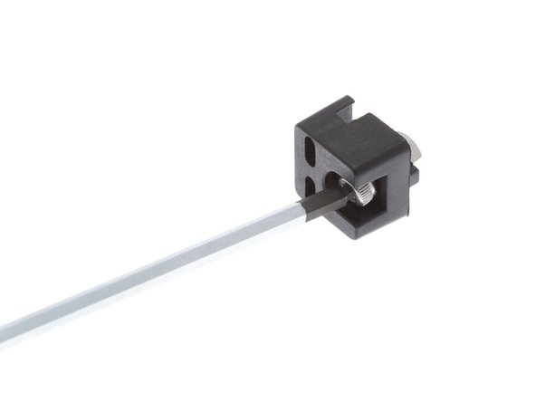
Begin by preparing the end stop mounts.
-
3 of them are used to mount the end stop switch at the top of the frame.
-
The other 3 are used to prevent the carriage from sliding off the linear rail on the bottom.
-
-
-
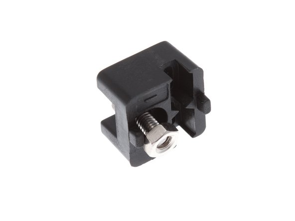
Pre-Thread M3 x 8mm SCHS onto End Stop Holder.
-
IMPORTANT: It will be very difficult to install this screw after the switch is installed.
-
-
-
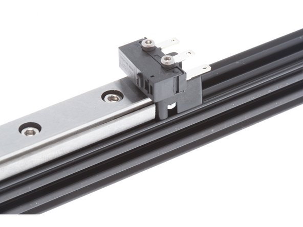
Microswitches are used to indicate the machine's "home" position.
-
During startup, the machine moves all 3 axis upwards until the switches are triggered. Triggering this switch tells the machine its initial starting position.
-
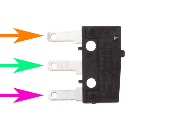
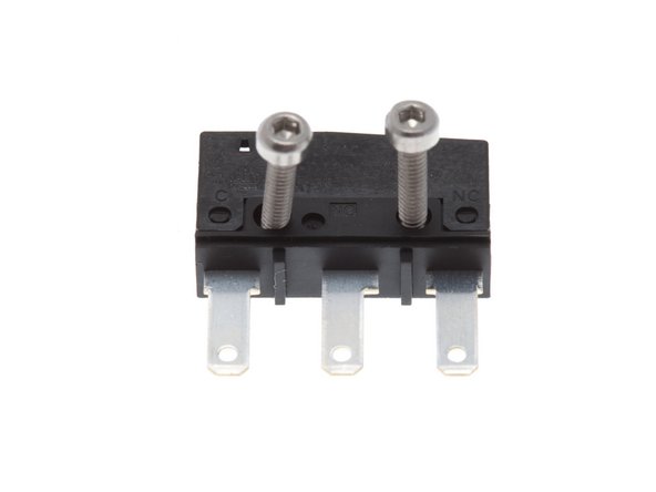
Note the terminal labels:
-
C (Common)
-
NO (Normally Open)
-
NC (Normally Closed)
-
We wire our end stop cabling to Common and Normally Closed. This means the switch will conduct electricity between these two terminals until the button is pressed. This way, broken wires will show up as a triggered switch press, thus signalling a fault.
-
-
-
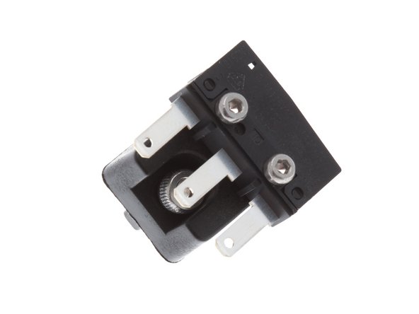
Install 2x M2 x 14mm SHCS into switch.
-
The end stop switch will function regardless of which direction the screws are inserted.
-
It is recommended to install them from the side with the switch terminal annotation, to make wiring easier.
-
-
-
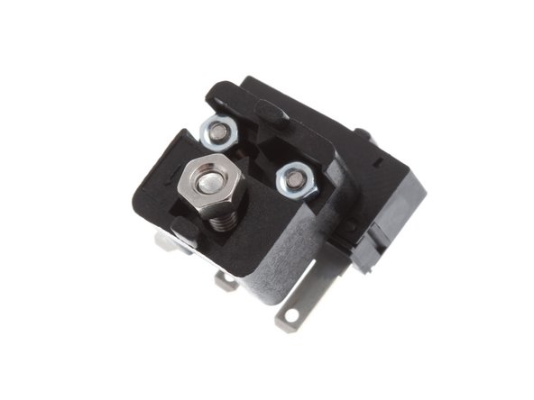
Attach switch to the end stop holder as shown on the right, using 2x M2 Nuts
-
Leave the switch a little loose; we'll do final positioning later before tightening down switch.
-
-
-
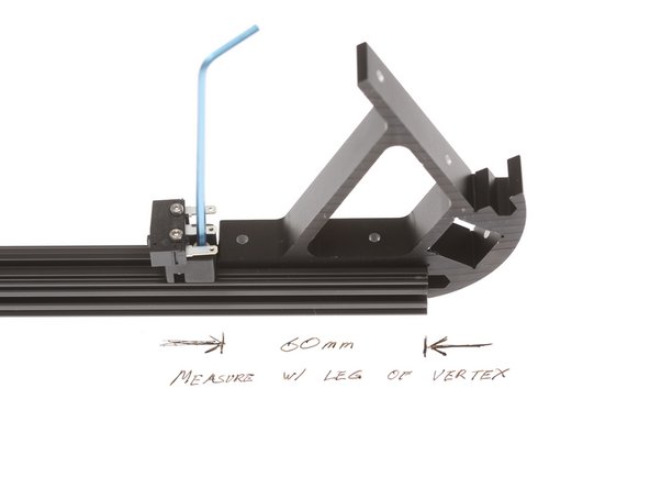
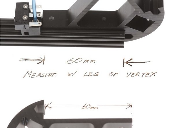
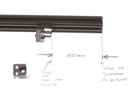
Positioning of the end stop switch block is critical. These switches define the XYZ coordinate of the printer system and the firmware expects it in a certain spot in order for the auto levelling system to deploy and retract the mechanical probe correctly.
-
Place the tail edge of the end stop switch holder 60mm from the edge of the extrusion.
-
Conveniently, the leg of the vertex is 60mm; use one of the vertex legs to measure and space the end stop holder.
-
Lock down the holder securely with the 2.5mm hex key.
-
-
-
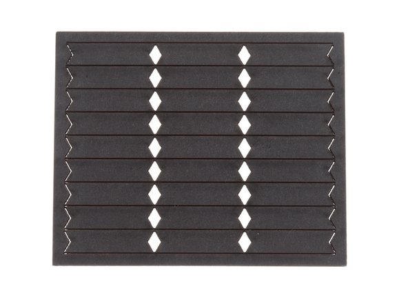
Slide nuts and nut spacers into the OpenBeam extrusion's T-Slot.
-
Each stack should start and end with a nut
-
THere are 23 nuts and 22 nut spacers.
-
We intentionally cut the nut spacers slightly undersized (on the minus side of tolerances). As you install the nuts, subsequent nuts and spacers downstream will move slightly and “fix itself”. If we didn’t do this, we’d end up with an interference situation (if the parts came in on the plus side of tolerances).
-
-
-
Be extremely careful not to let the carriage slide off the end of the rail. This could result in loss of bearings.
-
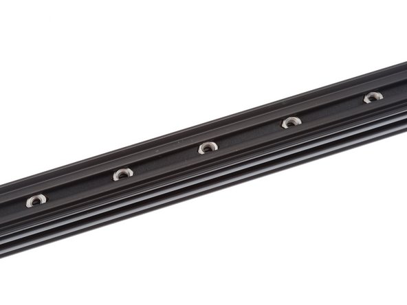
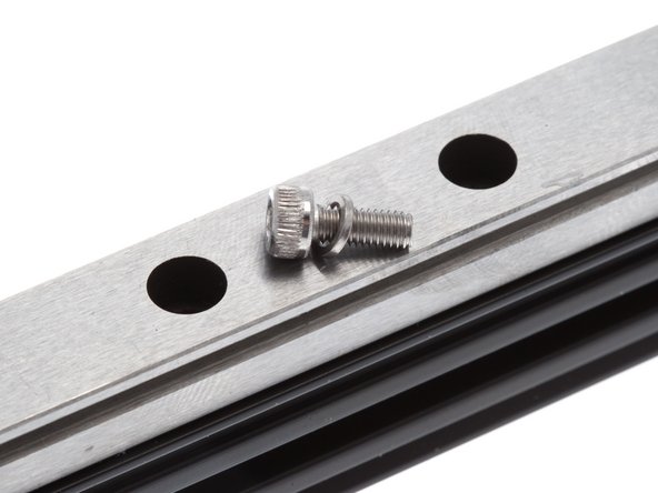
Each M3 x 8mm SHCS goes through an M3 Lock Washer before going into the counterbore hole. See picture for fastener stack for the linear rail.
-
The lock washer is critial - omitting it will cause the screw to bottom out and not fastener the linear rail correctly to the frame.
-
Slide the extrusion up against the top end stop switch holder, and center the linear rail on the width of the OpenBeam extrusion.
-
Starting from the end , PRIOR to installing the M3 x 8mm SHCS and M3 Lockwasher, insert the 2mm hex driver in to center the nut under the counterbore hole.
-
Drop in an M3 x 8mm SHCS and a M3 Lock Washer, and lightly tighten the screw to hold the rail in position.
-
At roughly 25, 50, and 75% down the rail from the end stop switch, insert the 2mm hex driver (prior to screws being dropped in) to re-center the nuts underneath the linear rail.
-
Drop in an M3 x 8mm SHCS and M3 Lock Washer in these positions and lightly tighten the screw.
-
-
-
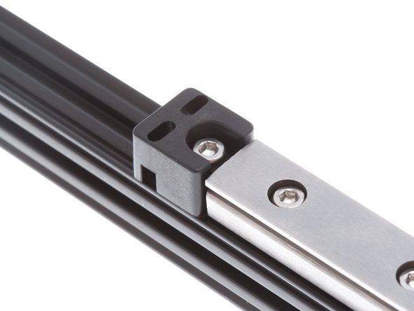
Install the empty endstop holders at the opposite end of the rail, using an M3 8mm SHC Screw & M3 Nut. Ensure that it is snug against the rail.
-
Be extremely careful not to let the carriage slide off the end of the rail. This could result in loss of bearings.
-
-
-
Recheck the centering of the rail on the OpenBeam Extrusion.
-
One handy way to do so is to use the edge of a pair of calipers to measure the lip of the extrusion on the rail.
-
The rail width is 12mm, so there should be 1.5mm on each side.
-
Install the fastener stack, and tighten down each screw snugly.
-
-
-
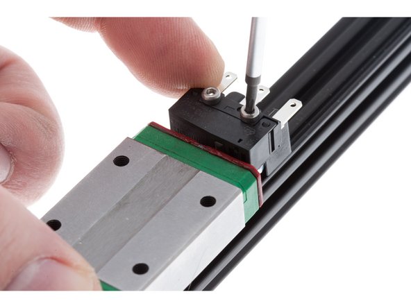
Confirm that end stop switch is loosely held and can move sideways.
-
Slide slider block on linear rail up against the top end stop switch holder plastic
-
With your fingers, wriggle the switch around until you hear the switch activate with an audible "CLICK"
-
While holding the switch in place, tighten the two M2 x 14mm SHCS holding the switch
-
Verify functionality by sliding the slider block down and back up again. You should hear the switch click.
-


Cancel: I did not complete this guide.
3 other people completed this guide.
One Comment
My kit did not have the nut spacers. Not really needed. Put washers in all holes, then screws, then 1.5 turns when installing nuts. Then slide into Openrail, align, then tighten all bolts
Kent Gaddy - Resolved on Release Reply