
Introduction
The Lower Triangle houses the motor, cold end extruder, bed clamps and electronics for the Kossel Pro 3D printer. Along with the Upper Triangle and Drive Towers, the Lower Triangle forms the frame of the printer.
-
-
The components referenced in this document comes from the following kits:
-
ZT-KIT-00116 - Chassis Upgrade Kit - Vertexes
-
ZT-KIT-00153 - Kossel Sundries - Nut Spacers
-
ZT-KIT-001xx - OpenBeam Reprap Fastener Pack - Nuts and screws
-
ZT-KIT-00132 - Pulleys
-
Depending on the size of the printer you are building, the extrusions may come from:
-
ZT-KIT-00187 / ZT-KIT-00188 - Mini Kossel Extrusions, Clear / Black
-
ZT-KIT-00239 - Kossel Extrusions, Black
-
-
-
Like every T-Slot construction system, it is necessary to pre-plan the insertion of extra nuts for future expansion.
-
Faces highlighted have their ends capped off after assembly, and it is a good idea to insert additional nuts into these channels PRIOR to assembling the subassembly.
-
The only exception is the face highlighted in blue. This face will be used for electronics mounting. Here, insert 2x M3 x 10mm or M3 x 6mm hex head cap screws, found in the Brainwave Pro mount accessory pack, in Kossel Common Core Components kit.
-
We suggest inserting a minimum of 6 M3 nuts, to allow for the addition of 2 OpenBeam brackets. You have been supplied with a copious amount of M3 nuts and you may insert more.
-
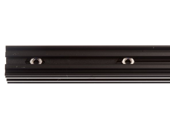
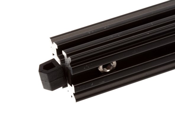
Using the provided set screws, secure the stack of nuts in the center of each extrusion face as shown on the right to prevent rattling and the nuts falling out while maneuvering the extrusion during the build process.
-
-
-
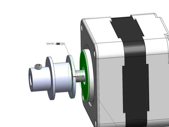
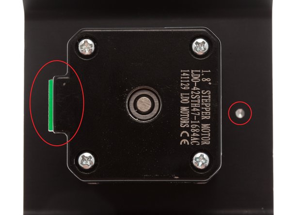
The distance between the flange of the timing belt pulley and the flange highlighted on the stepper motor should be 5mm (+/- 1mm).
-
Setting this distance is important to ensure that the belts will be centered correctly when installed.
-
To create a stackup of approximately 5mm, locate the following components and stack them as shown:
-
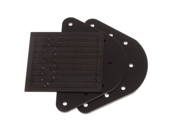
Laser cut spacer, from the Sundries Bag, in Kossel Common Core Component Kit
-
Vertex Cover Plate, from the Kossel Chassis Upgrade Kit
-
-
-
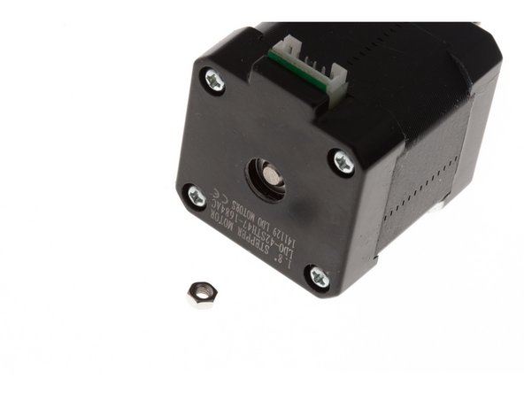
The motor shaft is sprung, which interferes with our ability to get a good press fit onto the motor.
-
To prevent this, use a single M3 nut and place it under the shaft while pressing the pulley on to prevent motion on the shaft.
-
-
-
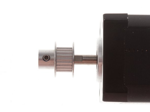
Place the component stackup as shown and press pulley on, keeping care to align set screw over flat on motor shaft
-
Secure pulley in place by tightening set screw.
-
-
-
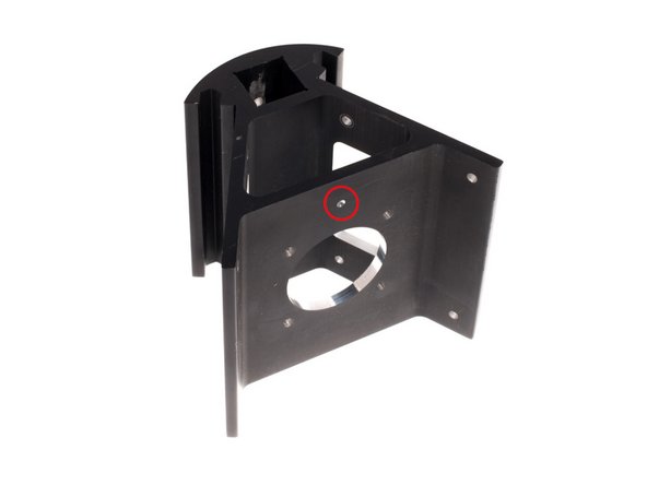
A machined lower vertex is shown on the right.
-
The dot machined onto the motor mount face denotes the side of the vertex that was clamped against the reference surface in our manufacturing fixture during machining.
-
It is recommended that you build the frame with all the dots facing the same side. We build our machines with the dots facing up, as that is the most accurate surface (due to its proximity to the reference surface in machining) and we build our machines with the motor connectors facing down (away from the dot).
-
-
-
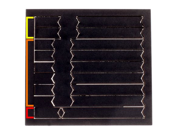
A set of laser cut nut spacers are included in your kit. These spacers positions the nuts at the correct spacing on the extrusion to allow for ease of assembly.
-
Kossel Pro Upper Vertex
-
Kossel Pro Lower Vertex / Kossel Reprap Vertexes
-
Vertical Drive Tower
-
-
-
Remember to preload the nuts to the center of the extrusion, as almost all the channels are capped off after installation!
-
Install the spacer and nut stack as shown to the right, using the spacers meant for the Kossel Pro Lower Vertex, on both ends of each of the extrusions.
-
-
-
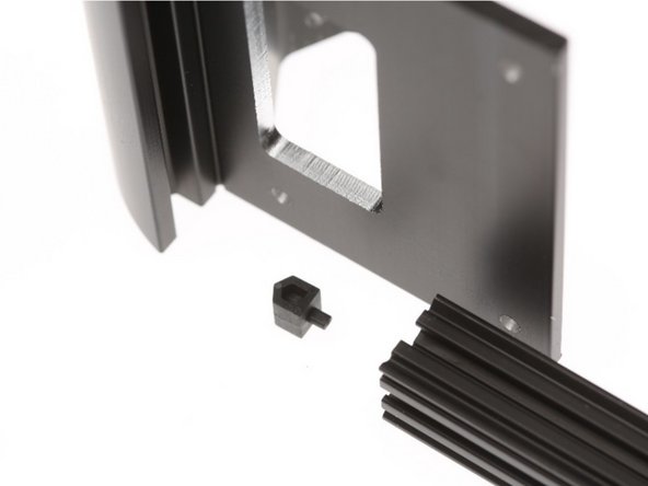
These Extrusion End Caps make it easier to load nuts into the channels.
-
Insert the pin on the extrusion end cap into the hole on the OpenBeam Extrusion as shown to the right.
-
-
-
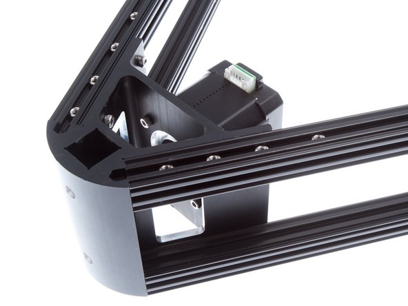
Carefully slide into Vertex.
-
Secure with 2x M3 x 8mm SHCS on each OpenBeam extrusion, 6 sides total, using the included ball-head 2.5mm hex driver.
-
Repeat for all 6 pieces of OpenBeam extrusion and all 3 vertexes.
-
-
-
Install Stepper Motor + Pulley set, using M3 x 8mm SHCS. Make sure that the motor connections all face the same way (away from the dot)
-
Using the nut loading feature on the vertex, slip 11 M3 hex nuts onto each of the lower OpenBeam extrusions.
-
-
-
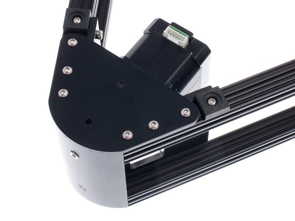
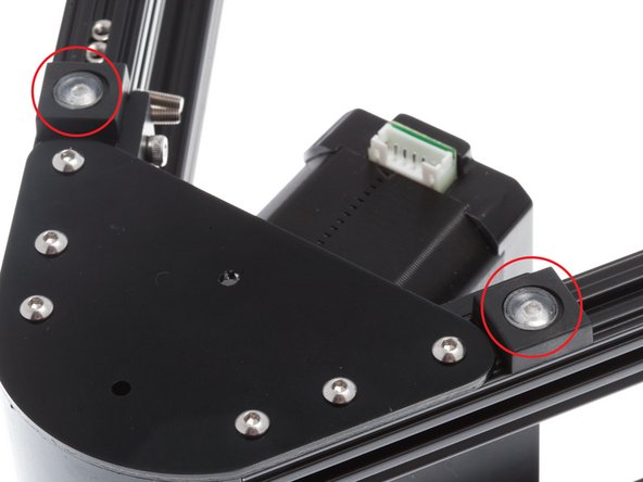
While you still have easy access, now is the time to prepare the screws that will connect the vertical towers
-
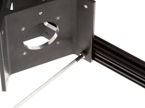
Insert two M3x8mm SHCS into the two holes on the outer edge of the vertex.
-
Loosely thread M3 nuts onto the screws. These will slide onto the vertical tower extrusions when they are inserted later on.
-
-
-
Using M3 x 6mm Button Head Cap Screws (BHCS), install vertex cap plates over the end of each vertex.
-
Install an OpenBeam Feet on each side of the vertex cap plate. Once the feet are in position, you may apply the rubber adhesive bumpon over the screw.
-
The rubber adhesive bumpon serves to dampen vibration from operation of the motor and prevent it from transmitting the vibration onto a table surface.
-
-
-
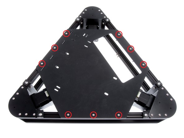
Finally, install the PSU mount plate. This is a loose plate packed into the Kossel Pro Kit (ZT-KIT-00229).
-
Install plate using 9x M3 x 6mm BHCS.
-
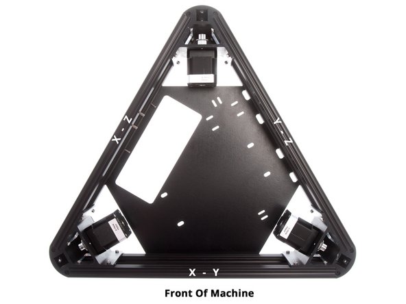
Note orientation of the rectangular opening. This should correspond to the side with the M3 x 10mm Hex Head Screws loaded; this is the access port for wiring access for the Brainwave Pro.
-
Textured side of the plastic should face downwards.
-
-
-
We are now ready to proceed to wiring and systems integration on the printer!
-


Cancel: I did not complete this guide.
One other person completed this guide.