
Difficulty
Moderate
Steps
14
Time Required
- Lower Triangle Electrical Wiring 14 steps

In Progress
This guide is currently being written. Reload periodically to see the latest changes.
Quiz
0
-
-
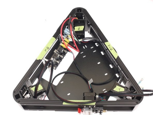
This documentation will make reference to the different sides of the printer frame. We follow Johann’s original designation for the vertex naming, shown on the right.
-
The “Front” of the printer is the side that faces the user, and where the extruder motor will be mounted. When facing the front of the printer, X is on the left, Y is on the right, and Z is the tower all the way in the back.
-
-
-
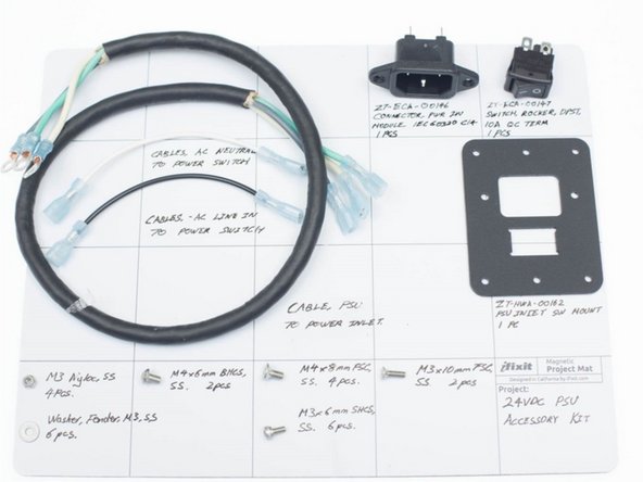
These parts are from ZT-ASY-00226 – Assembly, Power Supply Cables and ZT-ASY-00235 – Assembly, Power Inlet Module, located inside ZT-KIT-00124 – Kit, 24V 17A PSU
-
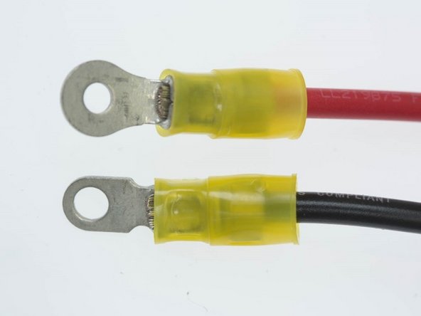
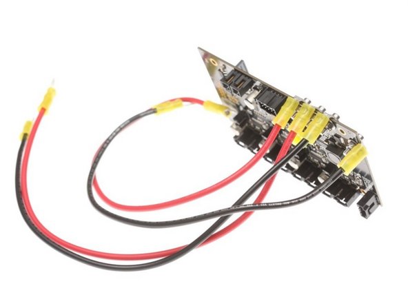
We provide heavy gauge, pre-crimped DC power cables for the printer. Note that there are two ends; one is for connection to the Brainwave Pro, one is for connection to the DC power supply (bigger hole, smaller OD).
-
-
-
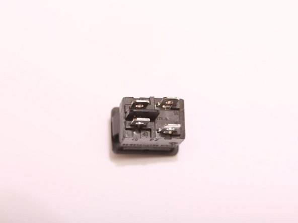
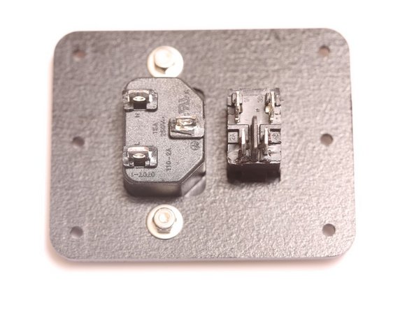
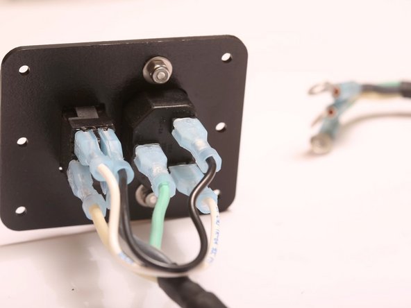
Here is the back side of the switch. This style of switch is called double-pole, single throw switch. This means that two individual circuits (poles) can be flipped one direction (throw) when the switch is flipped.
-
Note the connection names. When the switch is thrown, electrical contact is made between A – A’, and B – B’.
-
It is CRUCIAL that you wire this switch correctly, or a dangerous short circuit will result.
-
-
-
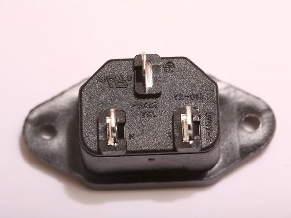
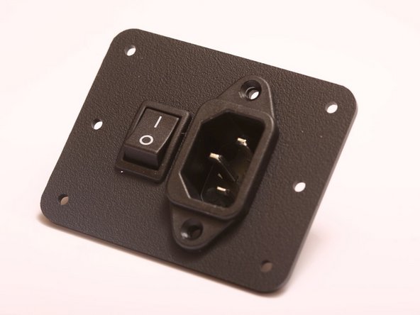
This is the IEC power inlet. IEC is an international standard set forth by the ISO governing power cords for various telecommunications instruments and devices.
-
AC power is transmitted over a Line and Neutral line. In the US, industry standard color code is as follows: Line = Black, Neutral = White. The safety ground circuit is denoted with a Green / Yellow insulator.
-
Newer Kits feature European / Chinese wire color coding. They are: Line = Brown, Neutral = Blue, Ground = Green/Yellow.
-
If you look closely, you will see the designations for the contacts molded in next to the contacts as well.
-
-
-
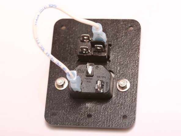
Snap components in place as shown on the right.
-
Secure IEC Power inlet with an M3 x 10mm FSC screw, a fender washer, and a nyloc nut, as shown to the right.
-
-
-
We’ll start by wiring the neutral wire to A’, as shown to the right.
-
Next, we’ll wire the line in to B’. This is the black wire on the right.
-
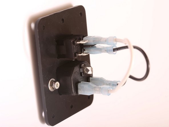
Next, we’ll wire the 3 conductor cable for carrying AC power from the switch to the PSU.
-
Connect the white (neutral) wire to A, black (line) wire to B, and connect the green grounding wire to the grounding terminal on the IEC power inlet.
-
Set this sub-assembly aside while we prepare our power supply unit for installation.
-
-
-
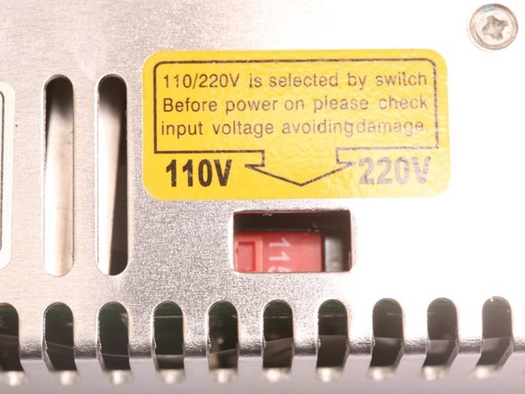
Set the input voltage on the PSU. This is located on the side panel, marked by a yellow label.
-
Failure to do this will result in the power supply not being able to supply enough power to turn the printer on.
-
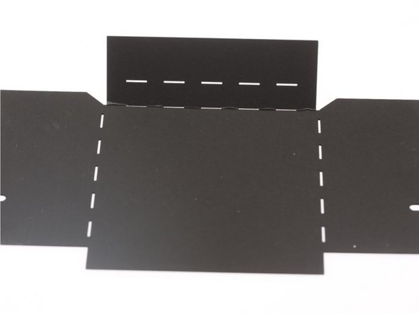
The cardboard duct redirects the cooling air from the cooling exhaust fan out the side of the printer. Without this duct, the cooling air will blow up directly at the heated bed, causing a cold spot to form on the HBP.
-
Fold the cardboard duct as shown to the right.
-
-
-
Refer to this guide for EzStruder assembly
-
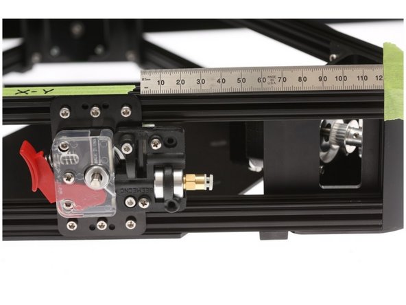
Install the EZStruder on the XY Face of the lower triangle
-
Edge of the OpenBeam NEMA17 Bracket should be 120mm from the edge of the lower kossel vertex, as shown in the photograph.
-
-
-
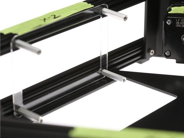
Place the "Clear license plate holder" part over the hex head cap screws to align the screws.
-
Position the mount. the edge of the "clear license plate holder should align roughly with the triangular opening in the power supply mount.
-
Tighten the standoffs onto the hex head cap screws, as shown to the right.
-
-
-
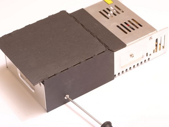
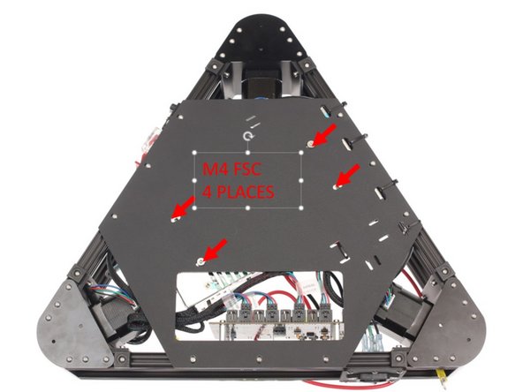
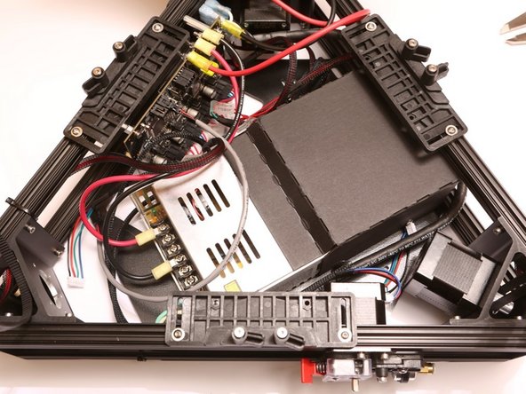
Holding the PSU, flip the lower triangle over and secure the PSU in place with 4x M4 FSC, included in the PSU Kit.
-
-
-
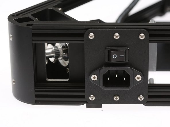
Loosen up some of the pre-loaded nuts, and install the power inlet panel as shown on the right, on the X-Z side of the printer.
-
Power inlet panel should sit between the vertex and the edge of the “license plate holder”
-
-
-
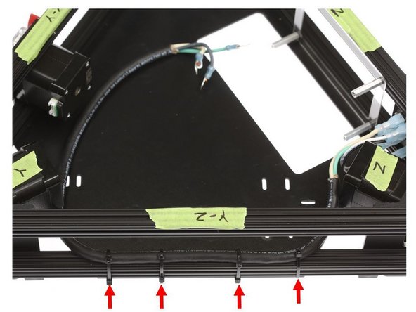
Daisy-chaining the included zip ties, secure the AC wiring bundle to the lower Y-Z OpenBeam extrusion on the printer, looping the zip tie through the oval opening on the power supply mount panel.
-
-
-
At full power, the lines from the power supply and to the heated bed approaches 17A - more current than in a household circuit!
-
It is CRUCIAL that the wiring is secure to prevent electrical faults
-
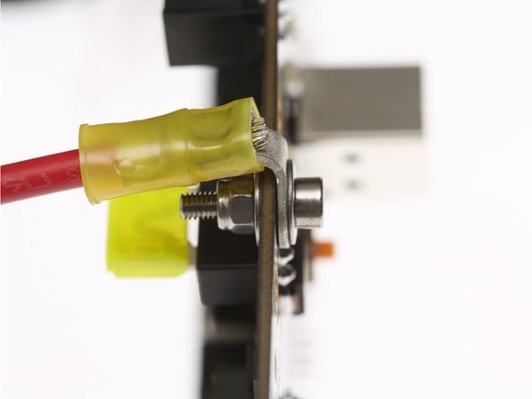
Review the picture of the fastener stack - screw head, fender washer, ring terminal, board, fender washer, nyloc nut)
-
On the heavy red and black cable, one terminal eyelet may be bigger than the other. Reserve the bigger diameter hole eyelet for the power supply / HBP side.
-
Attach the wires to the Brainwave Pro board, then fold the contacts over the PCB edge as shown with the wire ferrule facing up
-

Cancel: I did not complete this guide.
One other person completed this guide.
One Comment
The Brainwave DC power wiring in these instructions shows two red cables and two black cables, however mine only came with one red and one black. Hopefully that's correct.
Dive Laser - Resolved on Release Reply