
-
-
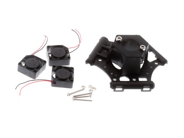
The new end effector kit is sold as a "kit of kits". Each individual bag of parts is available as a separate kit on Amazon.com, in case anyone needs spare / replacement parts.
-
-
-
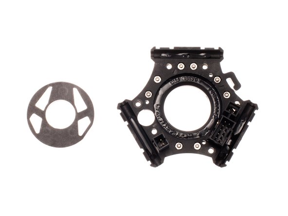
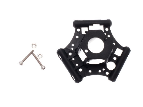
From the bag labeled: "End Effector Rebuild Kit", remove the 3 pieces of the end effector housing.
-
NOTE: It may be easier to install these nuts and screw one at a time.
-
Insert 6x M3 Nuts into position shown.
-
Secure nuts in position with M3 x 8mm SHCS, threaded in 3-4 turns.
-
We are just using these M3 x 8mm SHCS to temporarily hold the M3 nuts in place; they will be removed later, so no need to tighten the screws all the way.
-
Alternative technique would be to slide the assembly off the table and insert the screws from the bottom, using gravity to hold the nuts in position while the screws are installed.
-
-
-
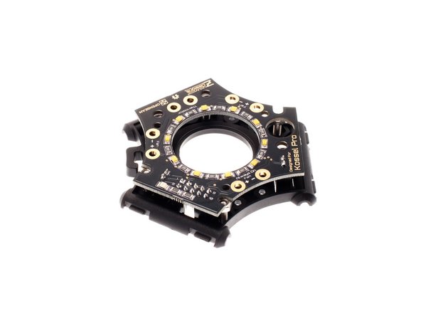
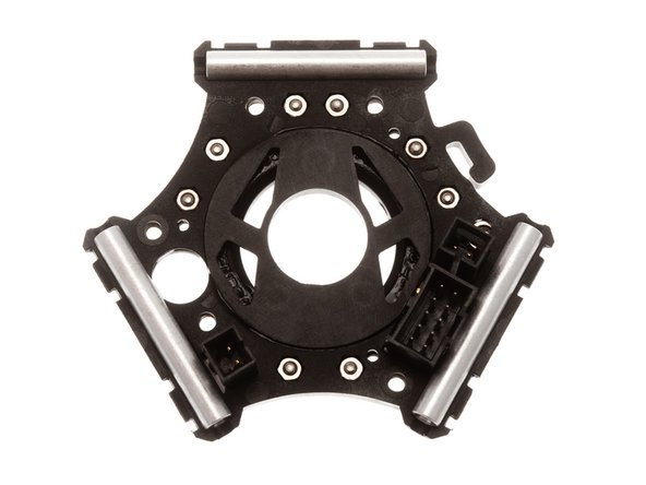
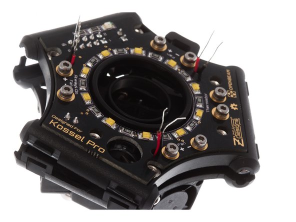
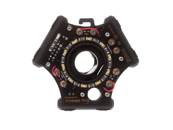
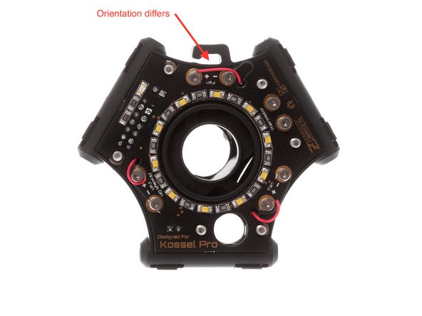
Using the round hole for the auto levelling probe, rotationally key the end effector PCA to the correct orientation.
-
Note: Some beta testers reported that it is easiest to lay the PCA down on the work surface with the connectors facing up and carefully press the plastic housing down over the connectors, working at clearing one connector at a time.
-
-
-
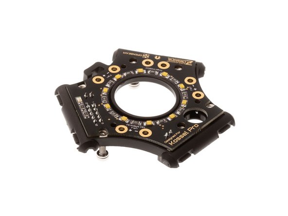
Flip the subassembly back over with PCA side facing up, and give each SHCS a tug to ensure that each nut is properly seated within its hexagonal cutout.
-
Press the end effector PCA all the way down against the plastic.
-
-
-
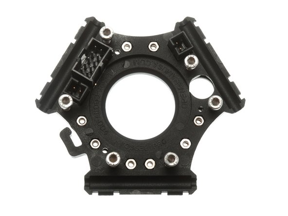
Flip the plastic back over again, until PCA side faces down.
-
Install 8x M2 nuts as shown.
-
As you install each nut, secure it by inserting an M2 x 6mm SHCS and an M2 washer from the opposite side.
-
Remove the M3 x 8mm nuts installed in previous steps to secure the nuts; these nuts are now fully captured and can't come loose.
-
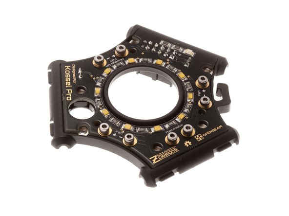
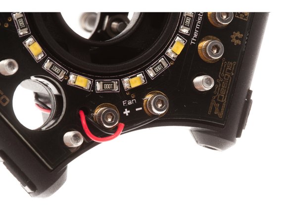
Lightly tighten down all the M2 screws onto their pads on the PCA.
-
You have just completed the electrical wiring terminals for the end effector. Due to the low height requirement, we are using this "screw terminal" design for connecting our power and signal lines.
-
-
-
Apply glue to the inner ring of the end effector and the 3 stand off mounts as shown.
-
Place plastic inner duct into circular indentation and line up the flat edge of the duct against the flat edge of the connector.
-
Press 3x M3 x 37mm standoffs into the plastic shell.
-
Set this lower assembly aside to dry. Minimum drying time 15 minutes, before additional handling. Do not place into enclosed plastic bag until degassing of the adhesive is complete (24 hours).
-
-
-
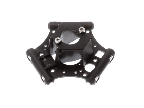
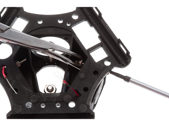
Thread 2x M3 x 18mm SHCS through the top of the end effector, and secure with M3 nuts, threading the screw 3-4 turns past the nut to ensure that it will not fall out accidentally.
-
-
-
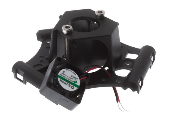
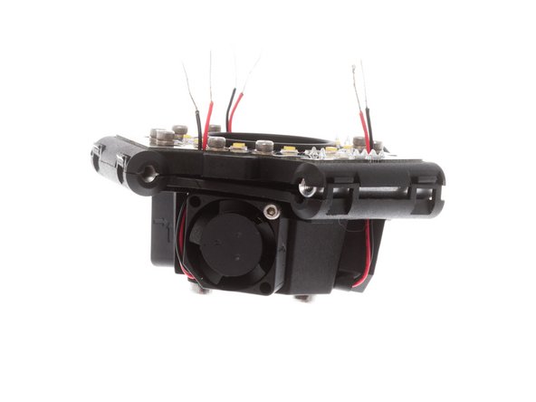
All fans should be installed with label side facing inwards.
-
Look for the absent of a plastic peg holding the fan, that is the corner that the wires should go.
-
Thread thee red and black cable through the small hole on the end effector top housing.
-
Secure fans with M2 x 16mm SHCS and M2 nuts.
-
Dab a bit of Loctite 410 on the inside threads of the end effector fans to prevent the screws from loosening during operation.
-
-
-
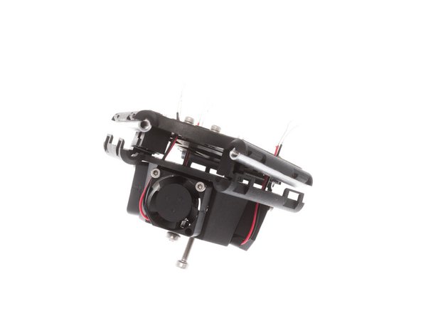
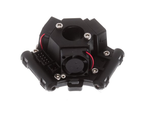
Verify that all 3 fans are installed, and give each fan a spin to make sure none of the housings have been crushed.
-
Fish fan cables through upper and lower plastic and through lower PCA.
-
Verify that the standoffs and the duct are glued on.
-
-
-
WARNING: Due to the high glass content of the plastic, snapping the two together is a one-time affair. Please go through the following check list before proceeding.
-
Verify that 6x M3 nuts are installed underneath the end effector PCA.
-
Verify that 8x M2 nuts and M2 x 6mm SHCS are installed to form the power contacts on the end effector PCA.
-
Verify that standoffs and plastic duct are glued in.
-
Verify that hot end mounting studs are installed.
-
-
-
NOTE! I only have one hand on the end effector here. The other hand was holding the camera. In reality, you’d want to do this with both hands.
-
Line everything up and get the snaps as close together as possible.
-
One side at a time, apply even pressure simultaneously on both sides of the snap, directly over the snap in the area indicated with red arrows.
-
Repeat for all 3 sides.
-
The snaps may crack slightly but the end effector will hold (there are screws as well holding the assembly together)
-
Install 4x M3 x 12mm SHCS (if using auto levelling probe) or 6x M3 x 12mm SHCS if using FSR Auto Levelling.
-
-
-
Loosen each M2 screw by about 2 turns. Using the tip of the screw driver, tuck the tinned ends of the cable under the screw.
-
Note: It is helpful to wrap the wire clockwise, when looking down on the end effector, tucking the wires under the washer. This way the cable is pulled tight upon tightening of screw.
-
Holding wire down in place to relief tension, tighten screw, and if necessary, use the tip of the driver to press the wire against the inside of the screw.
-
Note polarity; fans are polarity protected and will not function if polarity is reversed.
-


Cancel: I did not complete this guide.
2 other people completed this guide.
One Comment
At Step 3/Step 4 you are instructed to press the circuit board onto the effector. In the very first assembly instructions you were told to glue the spacers into the effector. One of these spacers interferes with insertion of the large connector into the effector. I had to remove that one spacer to install the circuit board and then glue it back on again afterwards.
Dive Laser - Resolved on Release Reply